
✖
![]()
![]()
![]()
![]()
![]()
![]()
ある程度きちんと網羅されたのがなかったので自分で書いていた。コード読みながら書いてるので、誤解がなければ正しいことが書いてあるはず。とはいえ完全に網羅できてない (electrical delay まわりとかの記述がまるっと抜けている)。
![]()
![]()
![]()
![ソニー 広角単焦点レンズ フルサイズ FE 28mm F2 デジタル一眼カメラα[Eマウント]用 純正レンズ SEL28F20 - ソニー(SONY)](https://m.media-amazon.com/images/I/41-tLipGfPL._SL500_.jpg)
ソニー 広角単焦点レンズ フルサイズ FE 28mm F2 デジタル一眼カメラα[Eマウント]用 純正レンズ SEL28F20 cho45
ソニー FE マウントは 55mm しか持っていなかったが、28mm もついに買ってしまった。FE マウントでは安い部類なのでさっさと買えばよかった。
![]()
![]()
![]()
![]()
![]()
![]()
memcached のデータが早々に消えることが多くなっていて困っていた。
https://lowreal.net/2016/12/14/2 で h2o の ssl-session-resumption のストア先を memcached にしているのが原因ではないか?と思ってやめてみたらなおった気がする。
![]()
![]()
![]()
NanoVNA (stm32f07) に対しての書きこみで、どの方法が早いのだろうか?と気になったので試した。対象は 95764bytes の ch.bin
結論からいうと SWD 経由の書きこみが早い。
(前もって DFU モードでブートする必要あり)
$ time dfu-util -d 0483:df11 -a 0 -s 0x08000000:leave -D build/ch.bin
dfu-util 0.9

Copyright 2005-2009 Weston Schmidt, Harald Welte and OpenMoko Inc.
Copyright 2010-2016 Tormod Volden and Stefan Schmidt
This program is Free Software and has ABSOLUTELY NO WARRANTY
Please report bugs to http://sourceforge.net/p/dfu-util/tickets/

dfu-util: Invalid DFU suffix signature
dfu-util: A valid DFU suffix will be required in a future dfu-util release!!!
Opening DFU capable USB device...
ID 0483:df11
Run-time device DFU version 011a
Claiming USB DFU Interface...
Setting Alternate Setting #0 ...
Determining device status: state = dfuERROR, status = 10
dfuERROR, clearing status
Determining device status: state = dfuIDLE, status = 0
dfuIDLE, continuing
DFU mode device DFU version 011a
Device returned transfer size 2048
DfuSe interface name: "Internal Flash  "
Downloading to address = 0x08000000, size = 95764
Download        [=========================] 100%        95764 bytes
Download done.
File downloaded successfully
Transitioning to dfuMANIFEST state
dfu-util -d 0483:df11 -a 0 -s 0x08000000:leave -D build/ch.bin  0.02s user 0.06s system 0% cpu 18.737 total
OpenOCD からデバッグではなくプログラムを書きこむ場合
http://openocd.org/doc/html/Flash-Programming.html#Flash-Programming これの通りだけど、基本的に program コマンドを使えばよい。
program の実装は https://github.com/ntfreak/openocd/blob/master/src/flash/startup.tcl で、いくつかのコマンドを呼びだすラッパーになっている。
stm32f0x だと stm32f0x.cfg で reset 直後に 48MHz クロックを起動して JTAG の最高速度を 8MHz まで上げている。
USB 経由と違って、いきなりコマンドを実行すれば書きこめる。
$ time openocd -f interface/stlink.cfg -f target/stm32f0x.cfg  -c "program ./build/ch.bin 0x08000000 verify reset exit"
Open On-Chip Debugger 0.10.0+dev-00930-g09eb941c (2019-09-14-00:35)
Licensed under GNU GPL v2
For bug reports, read
        http://openocd.org/doc/doxygen/bugs.html
Info : auto-selecting first available session transport "hla_swd". To override use 'transport select <transport>'.
Info : The selected transport took over low-level target control. The results might differ compared to plain JTAG/SWD
Info : clock speed 1000 kHz
Info : STLINK V2J34S7 (API v2) VID:PID 0483:3748
Info : Target voltage: 3.261130
Info : stm32f0x.cpu: hardware has 4 breakpoints, 2 watchpoints
Info : Listening on port 3333 for gdb connections
Info : Unable to match requested speed 1000 kHz, using 950 kHz
Info : Unable to match requested speed 1000 kHz, using 950 kHz
target halted due to debug-request, current mode: Thread
xPSR: 0xc1000000 pc: 0x080000c0 msp: 0x20000200
Info : Unable to match requested speed 8000 kHz, using 4000 kHz
Info : Unable to match requested speed 8000 kHz, using 4000 kHz
** Programming Started **
Info : device id = 0x20016448
Info : flash size = 128kbytes
** Programming Finished **
** Verify Started **
** Verified OK **
** Resetting Target **
Info : Unable to match requested speed 1000 kHz, using 950 kHz
Info : Unable to match requested speed 1000 kHz, using 950 kHz
shutdown command invoked
openocd -f interface/stlink.cfg -f target/stm32f0x.cfg -c 0.37s user 0.83s system 27% cpu 4.365 total 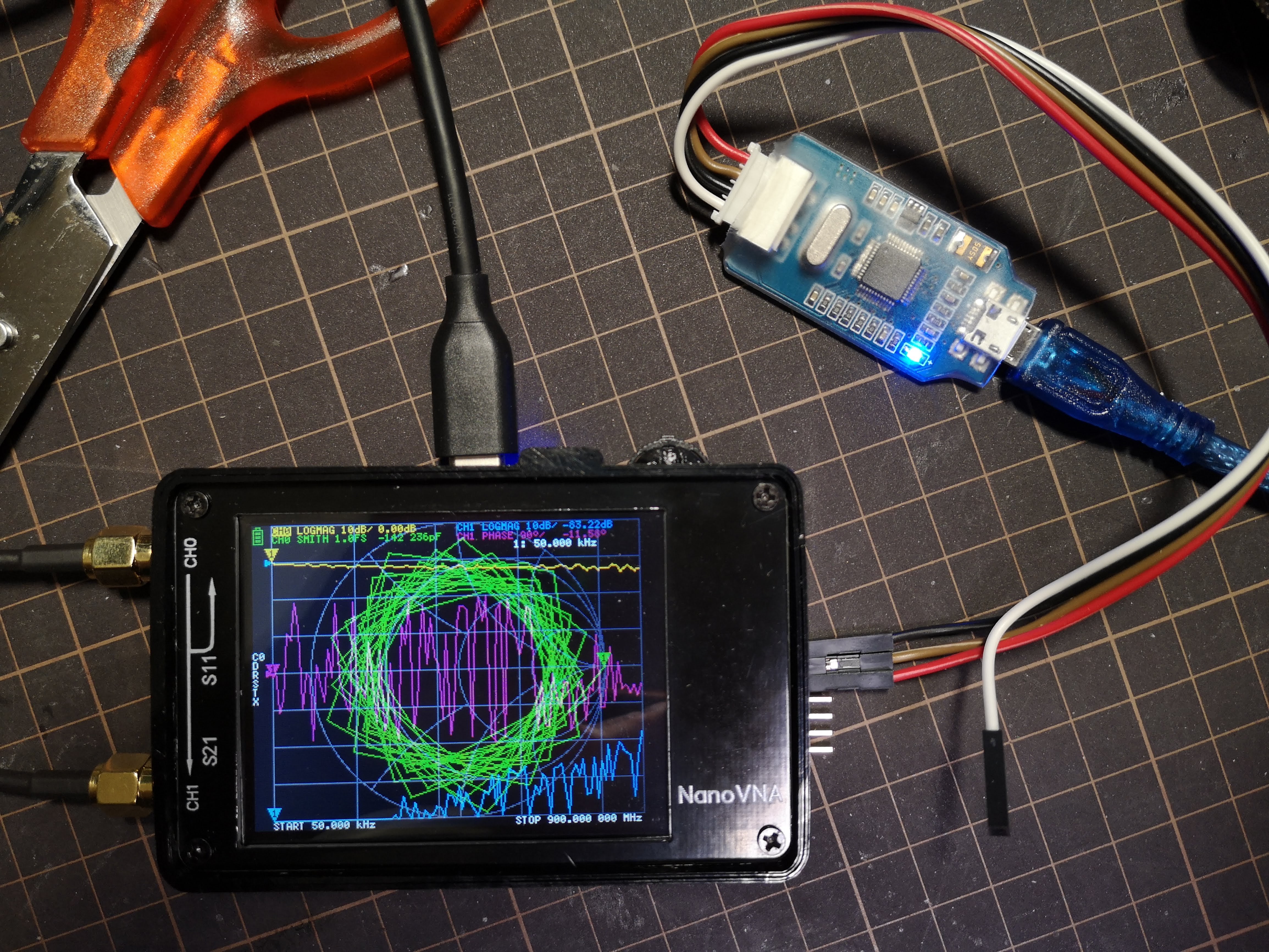
nRF51 で一回試したっきり使っていない怪しい J-Link OB
USB 経由と違って、いきなりコマンドを実行すれば書きこめる。デフォルト JTAG なので、ちゃんと SWD を指定しないとダメです。
$ time openocd -f interface/jlink.cfg -c "transport select swd" -f target/stm32f0x.cfg   -c "program ./build/ch.bin 0x08000000 verify reset exit"
Open On-Chip Debugger 0.10.0+dev-00930-g09eb941c (2019-09-14-00:35)
Licensed under GNU GPL v2
For bug reports, read
        http://openocd.org/doc/doxygen/bugs.html
swd
Info : J-Link ARM-OB STM32 compiled Aug 22 2012 19:52:04
Info : Hardware version: 7.00
Info : VTarget = 3.300 V
Info : clock speed 1000 kHz
Info : SWD DPIDR 0x0bb11477
Info : stm32f0x.cpu: hardware has 4 breakpoints, 2 watchpoints
Info : stm32f0x.cpu: external reset detected
Info : Listening on port 3333 for gdb connections
target halted due to debug-request, current mode: Thread
xPSR: 0xc1000000 pc: 0x080000c0 msp: 0x20000200
** Programming Started **
Info : device id = 0x20016448
Info : flash size = 128kbytes
** Programming Finished **
** Verify Started **
** Verified OK **
** Resetting Target **
shutdown command invoked
openocd -f interface/jlink.cfg -c "transport select swd" -f  -c   0.25s user 0.52s system 16% cpu 4.628 total
![]()
![]()
![]()
chromium Issue 884928: Web Serial API が該当する。(Chrome 系以外では実装されていない。予定もない)
実は Chrome Stable 77 でも、既に chrome://flags/#enable-experimental-web-platform-features を有効にしていると navigator.serial が生えてくるようになっている。
が、Android では(まだ)使えないみたいだ。上記イシューも Android がスコープに入っていない。
簡単に試せるページもある GitHub - GoogleChromeLabs/serial-terminal: Demo application for the Serial API.
ちなみに WebUSB での polyfill があったりする(これも google のレポジトリに入っている…) https://github.com/google/web-serial-polyfill けど、USB CDCはだいたいはOS側でインターフェイスを握られてしまうので、ドライバを無効にしたりしないといけないことに注意がいる。
現行では worker コンテキスト内で使うことができない。API 自体は有効なのだが、requestPort() してペアリングしたシリアルポートを、worker 内の getPorts で取得することができない。Issue 1005079: Serial Mojo interface not provided to Workers 報告したらイシューが立った。
また、上記に関連するのかもしれないが、そこそこ高速で通信を行うと容易にバッファが溢れてしまい、データの欠落が起こる。なので非常に大きなバッファを指定する必要がある。複数同時に read してもダメ。
![]()
![]()
![]()
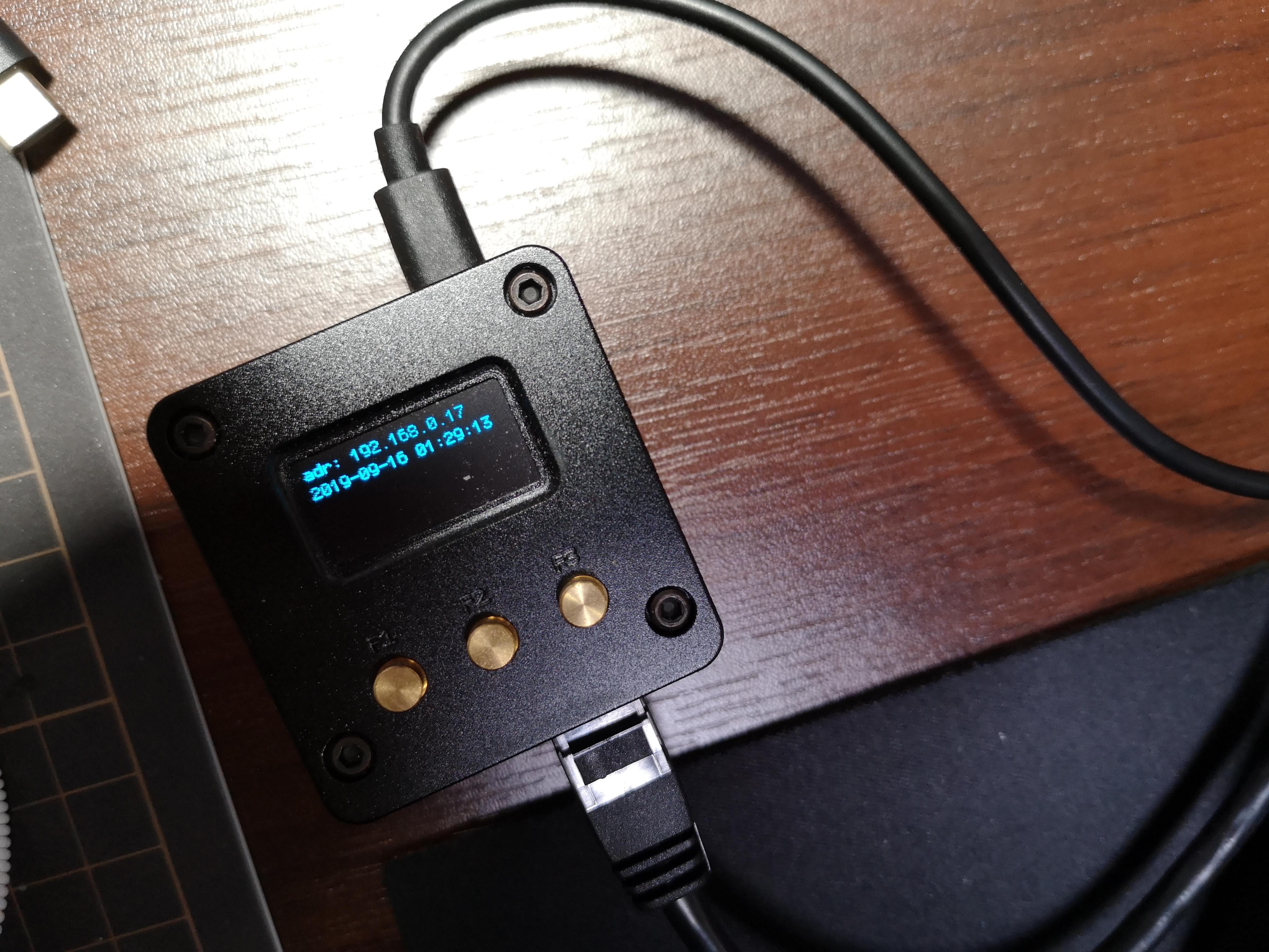
しばらく放っておいてどうセットアップしたか忘れたので、https://www.armbian.com/nanopi-neo-2/ armbian を改めて入れてみる。
FriendlyARM のイメージも結構更新されていそうだけど、どっちがいいか不明。しかし FriendlyARM のイメージはいまいちデキが良い感じがしなかったので、armbian Bionic server (Ubuntu系) を入れてみる。
Etcher で焼くだけ
ping 192.168.0.255 とかして arp -a して 02:01:a9 からはじまる Mac アドレスがそれ。
https://docs.armbian.com によると、デフォルトで ssh が起動しており、root 、 1234 で入れるらしい。
ssh root@192.168.0.xx
すると、初回設定としてパスワード変更とユーザ追加をさせられる。やったら一回 logout して、作ったユーザーでログインしなおす。
前後して
ssh-copy-id cho45@192.168.0.17
とかやっておく。
sudo armbian-config
して Personal -> Timezone の設定と、 System -> Hardware -> i2c0 にチェックを入れて再起動。
検出できるか確認しとく。
$ sudo apt install i2c-tools
$ sudo i2cdetect -y 0
     0  1  2  3  4  5  6  7  8  9  a  b  c  d  e  f
00:          -- -- -- -- -- -- -- -- -- -- -- -- --
10: -- -- -- -- -- -- -- -- -- -- -- -- -- -- -- --
20: -- -- -- -- -- -- -- -- -- -- -- -- -- -- -- --
30: -- -- -- -- -- -- -- -- -- -- -- -- 3c -- -- --
40: -- -- -- -- -- -- -- -- -- -- -- -- -- -- -- --
50: -- -- -- -- -- -- -- -- -- -- -- -- -- -- -- --
60: -- -- -- -- -- -- -- -- -- -- -- -- -- -- -- --
70: -- -- -- -- -- -- -- --
i2c グループに自分を追加しておく
$ sudo usermod -a -G i2c
# 一回ログアウトすること
$ i2cdetect -y 0
armbian もデフォルトでは root にしか gpio へのアクセス権限がなく、gpio グループなども設定されていない。ので自分でやる必要がある.
sudo groupadd gpio
sudo usermod -aG gpio cho45
$ sudo vim /etc/udev/rules.d/80-gpio.rules
SUBSYSTEM=="gpio", PROGRAM="/bin/sh -c '/bin/chown -R root:gpio /sys/devices/platform/soc/*pinctrl/gpio*'"
SUBSYSTEM=="gpio", PROGRAM="/bin/sh -c '/bin/chmod -R ug+rw /sys/devices/platform/soc/*pinctrl/gpio*'"
SUBSYSTEM=="gpio", PROGRAM="/bin/sh -c '/bin/chown -R root:gpio /sys/class/gpio'"
SUBSYSTEM=="gpio", PROGRAM="/bin/sh -c '/bin/chmod -R ug+rw /sys/class/gpio'"
sudo udevadm control --reload-rules
sudo udevadm test --action=change /sys/devices/platform/soc/1c20800.pinctrl/gpiochip1/gpio/gpio0
$ ls -altr /sys/class/gpio/
total 0
-rw-rw----  1 root gpio 4096 Sep 15 15:45 export
drwxrwxr-x  2 root gpio    0 Sep 15 15:45 .
drwxr-xr-x 51 root root    0 Sep 15 15:45 ..
lrwxrwxrwx  1 root gpio    0 Sep 15 15:45 gpio0 -> ../../devices/platform/soc/1c20800.pinctrl/gpiochip1/gpio/gpio0
-rw-rw----  1 root gpio 4096 Sep 15 15:45 unexport
lrwxrwxrwx  1 root gpio    0 Sep 15 15:45 gpio3 -> ../../devices/platform/soc/1c20800.pinctrl/gpiochip1/gpio/gpio3
lrwxrwxrwx  1 root gpio    0 Sep 15 15:45 gpiochip352 -> ../../devices/platform/soc/1f02c00.pinctrl/gpio/gpiochip352
lrwxrwxrwx  1 root gpio    0 Sep 15 15:45 gpiochip0 -> ../../devices/platform/soc/1c20800.pinctrl/gpio/gpiochip0
lrwxrwxrwx  1 root gpio    0 Sep 15 15:45 gpio2 -> ../../devices/platform/soc/1c20800.pinctrl/gpiochip1/gpio/gpio2
nodejs をいれる。apt でいれると気持ちわるいことになるので公式パッケージをいれるほうがよい。
$ cd ~/
$ mkdir app
$ cd app
$ wget https://nodejs.org/dist/v10.16.3/node-v10.16.3-linux-arm64.tar.xz
$ tar xvf node-v10.16.3-linux-arm64.tar.xz
$ ln -s  node-v10.16.3-linux-arm64 node
$ cd ~/bin
$ ln -s ~/node/bin/* .
$ sudo apt install pkg-config libcairo2-dev
$ git clone git@github.com:cho45/nanohat-oled-nodejs.git
$ cd nanohat-oled-nodejs
$ npm install
動作確認
$ node index.js
systemd 化
$ ./install.sh
$ ls /etc/update-motd.d
にある。/etc/update-motd.d/30-armbian-sysinfo が特に有用
![]()
![]()
![]()
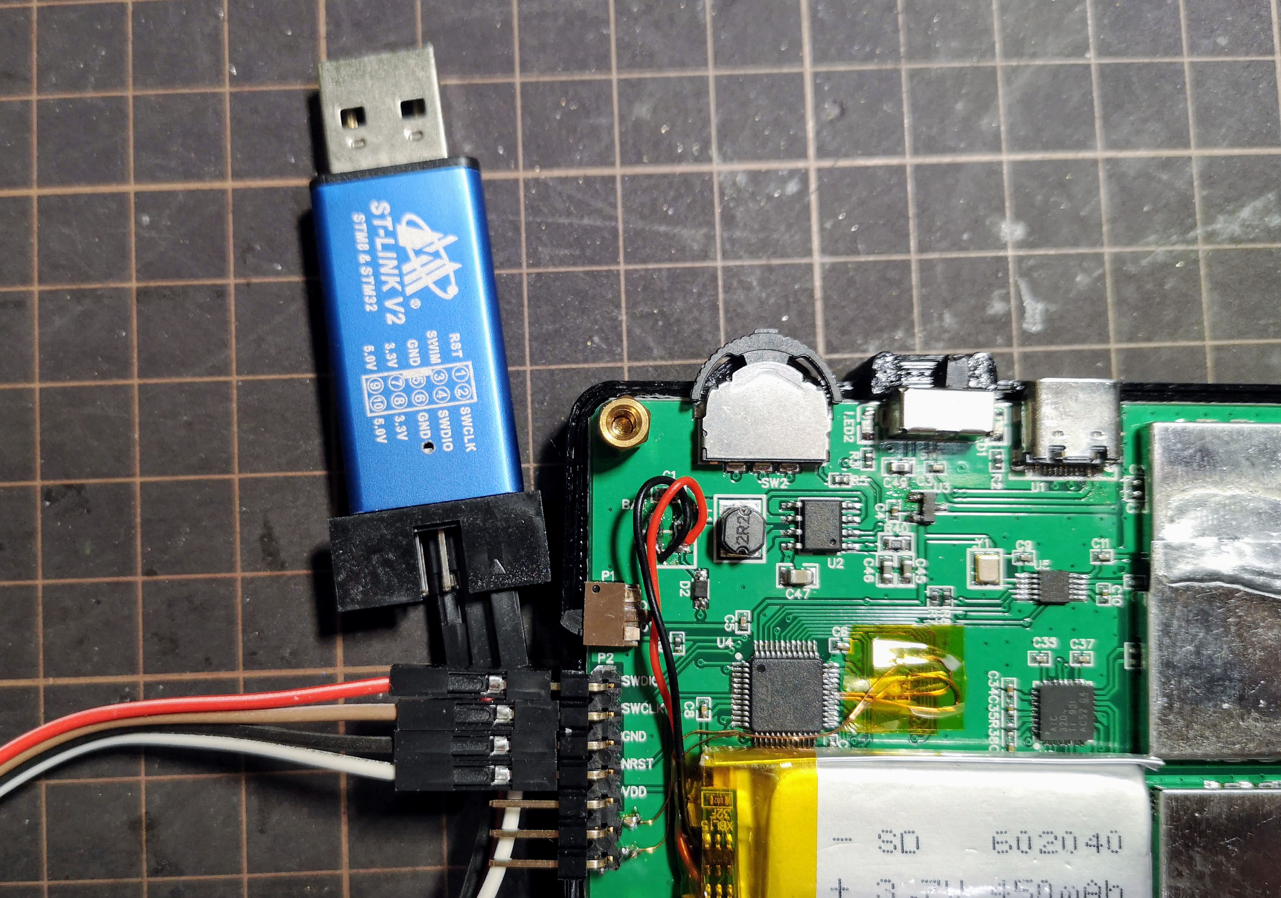
PCB上にピンヘッダ(未実装)がある。
SWD (Serial Wire Debug) 用のもの。ここに ST-Link を繋ぐ。ST-Link といっても中華 ST-Link だけど、こういう感じになる。
VCC 以外を接続する。VCCは普通に電源をオンにして供給する。
普通に make して build できる環境にしておく。arm-none-eabi-gcc が入っていればよい。
open-ocd は brew で入るデフォルトではなく、head を入れる必要がある。なぜか texinfo が要求されて死んだので前もって入れたほうがよさそう。
brew install texinfo
brew install open-ocd --HEAD
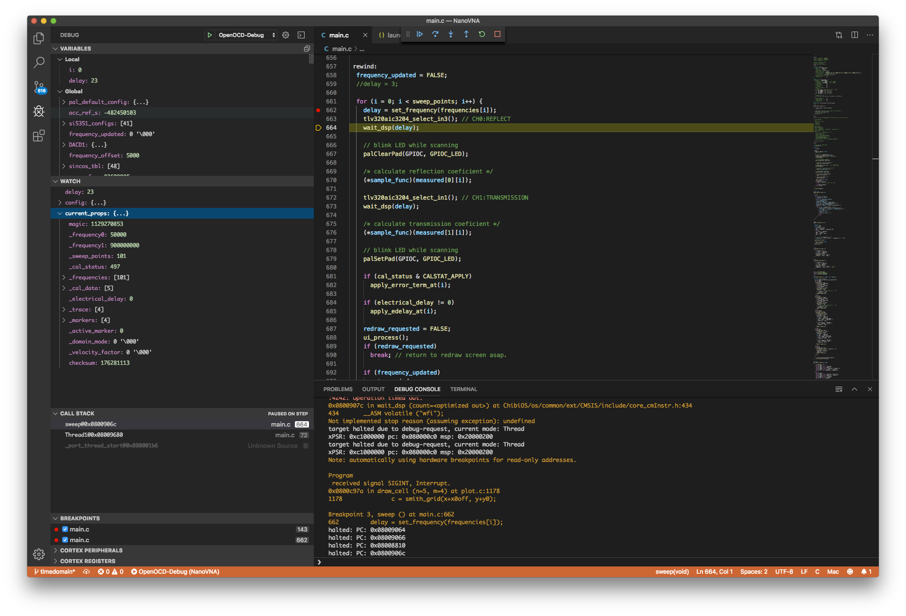
普段は vim を使っているが、CUI デバッガは個人的にはつらいので、こういうときは VSCode を使う。
VSCode を入れたのち Cortex-Debug extension を入れて使う。VSCode を開いて、Extensions から検索して Install するのが最速。
make を呼ぶようにしておく
{
    "tasks": [
        {
            "type": "shell",
            "label": "build",
            "command": "make",
            "args": [
            ],
            "options": {
                "cwd": "${workspaceRoot}"
            }
        }
    ],
    "version": "2.0.0"
} stlink を使って stm32f0x をデバッグするので以下のようにする。また、デバッグ前に build するようにする。
{
    "version": "0.2.0",
    "configurations": [
        {
            "type": "cortex-debug",
            "servertype": "openocd",
            "request": "launch",
            "name": "OpenOCD-Debug",
            "executable": "build/ch.elf",
            "configFiles": [
                "interface/stlink.cfg",
                "target/stm32f0x.cfg"
            ],
            "cwd": "${workspaceRoot}",
            "preLaunchTask": "build",
        }
    ]
} Debug を開いて Start Debugging (F5) をする。ビルドしたのち、しばらくする (デバイス側にビルドしたファームが転送される) とデバイス側の画面は白くなり、リセットハンドラでブレークするので、適当な場所にブレークポイントを置いて resume する。
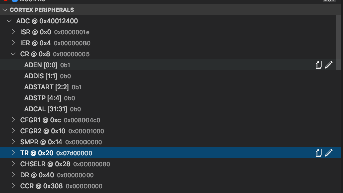
追加で SVD (System View Description) ファイル (ST のサイトからダウンロードできる を指定しておく。
"svdFile": "./STM32F0x8.svd",
MCU のレジスタがわかりやすく表示される
/usr/local/share/openocd/scripts/
にある。結構 deprecated になっているものも置いたままだったりする。stlink.cfg は ST-Link のバージョンに関係なく共通で使えるものになっている。
リソース
![]()
![]()
![]()


SteelSeries ゲーミングマウスパッド ブラック 小型 ノンスリップラバーベース 25cm×21cm×0.2cm QcK mini 63005 cho45
会社のマウスとマウスパッドを買い替えた。前まで SteelSeries QcK (mini じゃないやつ) を使ってたけど、普段全面を使うことはまずないので mini にしてみた。
![]()
![]()
![]()
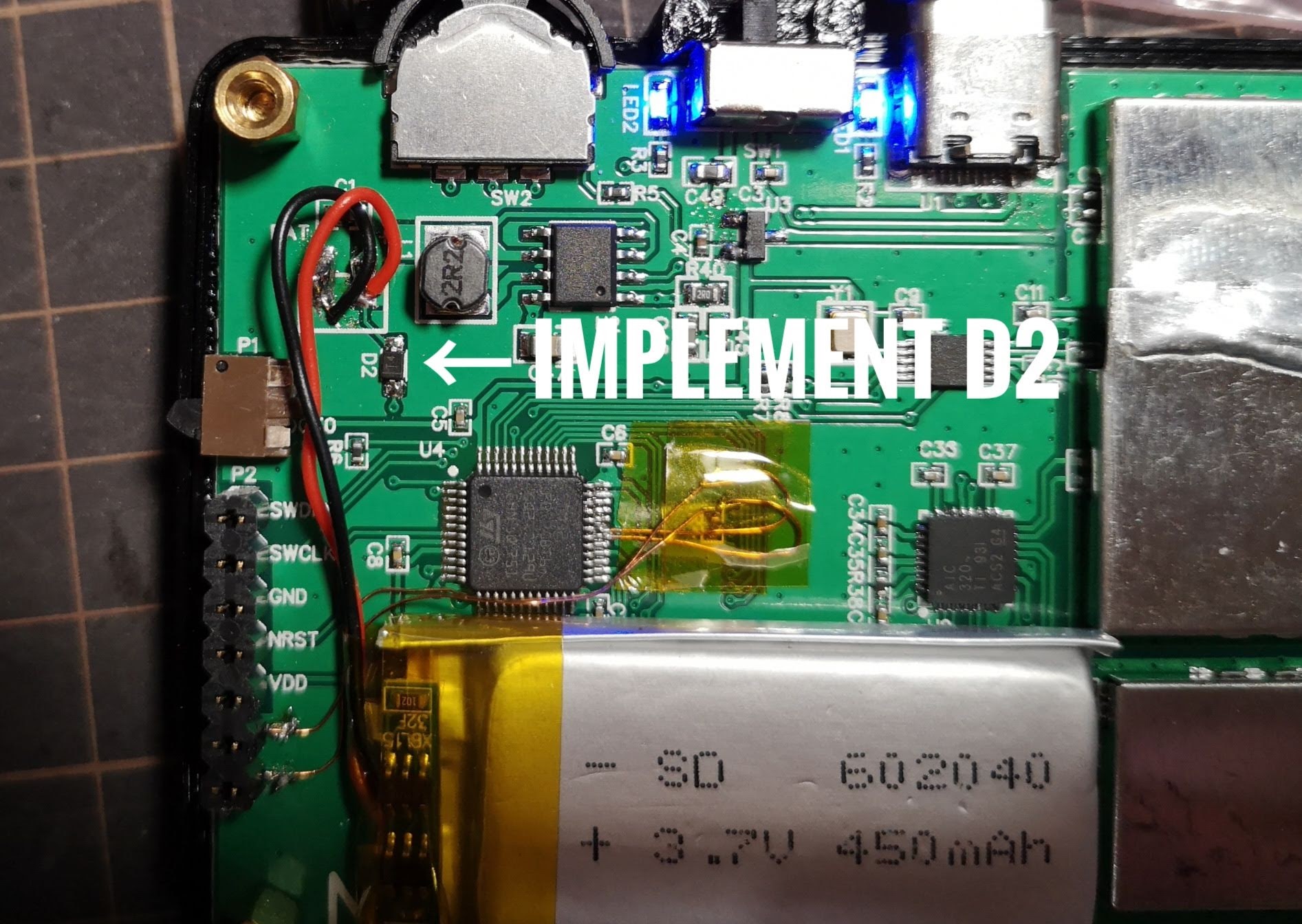
回路図の D2 はバッテリーから MCU の VBAT に接続する経路ですが、自分の入手した固体だと未実装でした。せっかくなので、手元にあった適当なダイオードをひとまず半田付けして、ファームウェア側の実装を試してみました。使ったのは汎用小信号用ダイオードの 1N4148 の SMD 版 (SOD-323) ですが、本来はショットキーのほうが良いはずです。
.png)
D2 の実装が必要なことと、中華版のバッテリーが載っているモデルにしか適用できないので (一応 VBAT を見た結果、バッテリが載っていないあるいは D2 がない場合には無視するようにはしてありますが)、オリジナルの master には入れることができないパッチです。自分でパッチを管理する必要があります。
master に入れてもらったので、自分でパッチ管理する必要はなくなりました。ありがたや。D2 を実装したうえで最新ファームを書くだけで有効になります。
int16_t adc_vbat_read(ADC_TypeDef *adc)
{
#define ADC_FULL_SCALE 3300
#define VBAT_DIODE_VF 500
#define VREFINT_CAL (*((uint16_t*)0x1FFFF7BA))
	float vbat = 0;
	float vrefint = 0;

	ADC->CCR |= ADC_CCR_VREFEN | ADC_CCR_VBATEN;
	// VREFINT == ADC_IN17
	vrefint = adc_single_read(adc, ADC_CHSELR_CHSEL17);
	// VBAT == ADC_IN18
	// VBATEN enables resiter devider circuit. It consume vbat power.
	vbat = adc_single_read(adc, ADC_CHSELR_CHSEL18);
	ADC->CCR &= ~(ADC_CCR_VREFEN | ADC_CCR_VBATEN);

	uint16_t vbat_raw = (ADC_FULL_SCALE * VREFINT_CAL * vbat * 2 / (vrefint * ((1<<12)-1)));
	if (vbat_raw < 100) {
		// maybe D2 is not installed
		return -1;
	}

	return vbat_raw + VBAT_DIODE_VF;

}
一応 VREFINT_CAL を使って補正をかけています。面倒なので計算に float 使ってますが、返り値は mV 単位の int16_t です。
既存の adc_single_read() では ADC のサンプリングサイクルが最小になっているのですが、これだと VBAT から内部キャパシタを十分に充電できないようで、ADC で取得できる値がやたら低くく、うまくいきませんでした。ということで ADC_SMPR_SMP_239P5 までサイクル数を増やしました。
そんなに頻繁に残量をとってもしかたないのですが、面倒なので sweep 直後に毎回取得するようにました。
      if (vbat != -1) {
          adc_stop(ADC1);
          vbat = adc_vbat_read(ADC1);
          touch_start_watchdog();
          draw_battery_status();
} 5x7 のフォントとして残量アイコンを実装しようと最初は考えていましたが、小さすぎるので、自力でモリモリ描くことにしました。
void
draw_battery_status(void)
{
    int w = 10, h = 14;
    int x = 0, y = 0;
    int i, c;
    uint16_t *buf = spi_buffer;
    uint8_t vbati = vbat2bati(vbat);
    uint16_t col = vbati == 0 ? RGB565(0, 255, 0) : RGB565(0, 0, 240);
    memset(spi_buffer, 0, w * h * 2);

    // battery head
    x = 3;
    buf[y * w + x++] = col;
    buf[y * w + x++] = col;
    buf[y * w + x++] = col;
    buf[y * w + x++] = col;

    y++;
    x = 3;
    buf[y * w + x++] = col;
    x++; x++;
    buf[y * w + x++] = col;

    y++;
    x = 1;
    for (i = 0; i < 8; i++)
        buf[y * w + x++] = col;

    for (c = 0; c < 3; c++) {
        y++;
        x = 1;
        buf[y * w + x++] = col;
        x++; x++; x++; x++; x++; x++;
        buf[y * w + x++] = col;

        y++;
        x = 1;
        buf[y * w + x++] = col;
        x++;
        for (i = 0; i < 4; i++)
            buf[y * w + x++] = ( ((c+1) * 25) >= (100 - vbati)) ? col : 0;
        x++;
        buf[y * w + x++] = col;

        y++;
        x = 1;
        buf[y * w + x++] = col;
        x++;
        for (i = 0; i < 4; i++)
            buf[y * w + x++] = ( ((c+1) * 25) >= (100 - vbati)) ? col : 0;
        x++;
        buf[y * w + x++] = col;
    }

    // battery foot
    y++;
    x = 1;
    buf[y * w + x++] = col;
    x++; x++; x++; x++; x++; x++;
    buf[y * w + x++] = col;

    y++;
    x = 1;
    for (i = 0; i < 8; i++)
        buf[y * w + x++] = col;

    ili9341_bulk(0, 1, w, h);
}
vbat2bati は以下のような inline 関数です。閾値がいまいちわからないので、結構雑に設定してます。
// convert vbat [mV] to battery indicator
static inline uint8_t vbat2bati(int16_t vbat)
{
	if (vbat < 3200) return 0;
	if (vbat < 3450) return 25;
	if (vbat < 3700) return 50;
	if (vbat < 3950) return 75;
	return 100;
}
![]()
![]()
![]()
