GPIO ピンからとれる電源は普通に電源回路直結なので、Raspberry Pi 自体が起動していようがしていまいが、電源ケーブルさえ接続されていれば供給されています。まぁこれはいいんですが、Rasp...cho45
GPIO ピンからとれる電源は普通に電源回路直結なので、Raspberry Pi 自体が起動していようがしていまいが、電源ケーブルさえ接続されていれば供給されています。まぁこれはいいんですが、Raspberry Pi 本体が起動していないとき、もっというとそれらを扱うデーモンが起動していないときに電源供給されてもエコじゃないので、なんとかしました。
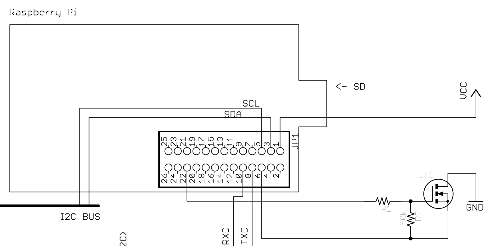
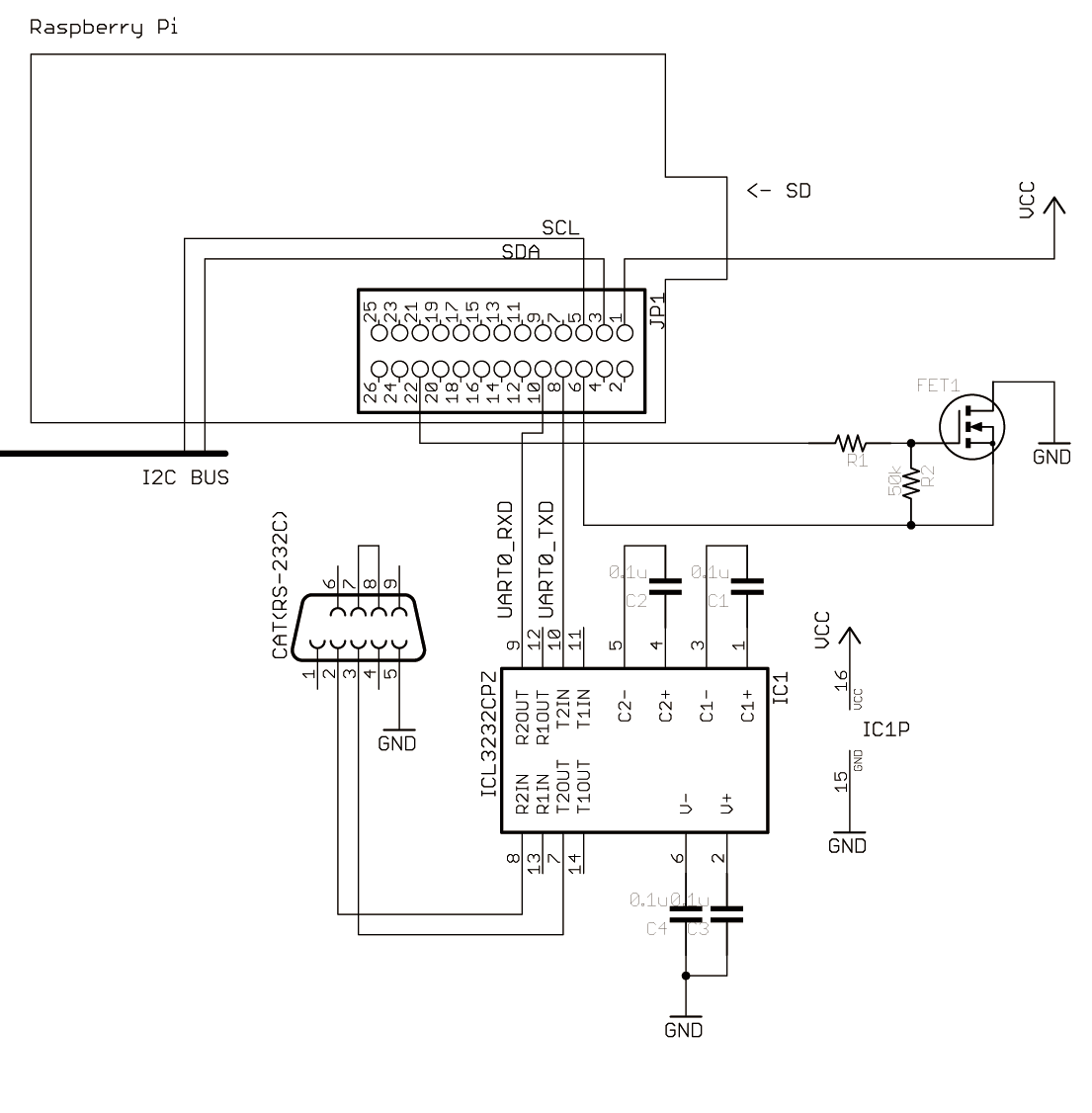
回路図
ちょっと余計な線がありますが、キモは FET だけです。伸びてる GND と VCC を周辺回路に繋ぐと、GPIO 25 (22pinから出てる) の論理によってオン・オフします。
手元では 2SK2796L を使ってます (3.3V で直接駆動できるので)
コード側
単に GPIO 25 ピンのハイ・ローを切り替えるだけです。Ruby の場合以下のように
#!/usr/bin/env ruby# coding: utf-8moduleGPIOdefself.export(pin)
File.open("/sys/class/gpio/export", "w") do|f|
f.write(pin)
endenddefself.unexport(pin)
File.open("/sys/class/gpio/unexport", "w") do|f|
f.write(pin)
endenddefself.direction(pin, direction)
[:in, :out].include?(direction) or raise "direction must be :in or :out"
File.open("/sys/class/gpio/gpio#{pin}/direction", "w") do|f|
f.write(direction)
endenddefself.read(pin)
File.open("/sys/class/gpio/gpio#{pin}/value", "r") do|f|
f.read.to_i
endenddefself.write(pin, val)
File.open("/sys/class/gpio/gpio#{pin}/value", "w") do|f|
f.write(val ? "1" : "0")
endendend
GPIO.export(25)
GPIO.direction(25, :out)
GPIO.write(25, true)
at_exit do
GPIO.write(25, false)
end
sleep 3# 周辺機器が安定するまで適当な時間
...
at_exit でローにするようにしてるだけです。
備考
回路図だとわかりにくい感じだけど、これは GND 側のスイッチ (ローサイドスイッチ) で、VCC は繋がりっぱなしなので、Raspberry Pi 以外の他の電源を回路に接続するとよくないかもしれないです。
// Slave memory map (must be smaller than 254 (0xfe) bytes)
uint8_t data[9];
// Enter to slave receive mode with data and size.
// After this operation, data will be changed automatically by TWI interrupt.
i2c_slave_init(0x65, data, 10);

// Access (set or get) to I2C data block
data[0] = 0x10;
// Or more readable code with struct
struct {
    uint8_t foo_flag1;
    uint8_t foo_flag2;
    uint16_t bar_value1;
    uint16_t bar_value2;
    uint16_t bar_value3;
    uint16_t bar_value4;
} data;

i2c_slave_init(0x65, &data, 10);
Raspberry Pi だ! ππだ!! Raspberry Pi は約5000円ぐらいで買うことができるカードサイズの Linux パソコンです。当然スペックとしてはしょぼいのですが、ホームサーバ...cho45
Raspberry Pi だ! ππだ!! Raspberry Pi は約5000円ぐらいで買うことができるカードサイズの Linux パソコンです。当然スペックとしてはしょぼいのですが、ホームサーバ用途とかには十分な感じです。
まぁそれだけでも安くて便利なボードなのですが、キモはさらに GPIO (General Purpose IO) がついているところです。基板にピンが立っていて、そのピンを Linux 側から制御できるので、マイコンの延長として使うことができます。普通、マイコンといえども性能が良かったり複雑なインターフェイスをつけようとすると、結構コストがかかるので、多少複雑なことをしたい場合、このような安い Linux コンピュータで比較的富豪的に諸問題を解決するのは個人レベルではかなりコストパフォーマンスが良い気がします。
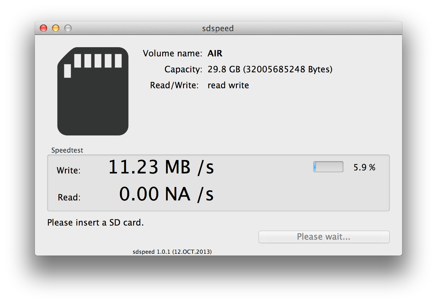
指定するのはあくまでディスクであって、パーティションではないところに注意が必要です (/dev/disk2s1 とかはパーティション)。df で出てくるのはマウント済みのパーティション一覧で紛らわしいので、diskutil list を使ったほうが良いです。dd で指定するディスクファイルは r (raw) をつけて指定します。
$ ssh pi@192.68.0.250
pi@192.168.0.250's password:
Linux raspberrypi 3.6.11+ #538 PREEMPT Fri Aug 30 20:42:08 BST 2013 armv6l

The programs included with the Debian GNU/Linux system are free software;
the exact distribution terms for each program are described in the
individual files in /usr/share/doc/*/copyright.

Debian GNU/Linux comes with ABSOLUTELY NO WARRANTY, to the extent
permitted by applicable law.
Last login: Thu Sep 26 07:18:58 2013
pi@raspberrypi ~ $
This file contains bidirectional Unicode text that may be interpreted or compiled differently than what appears below. To review, open the file in an editor that reveals hidden Unicode characters. Learn more about bidirectional Unicode characters
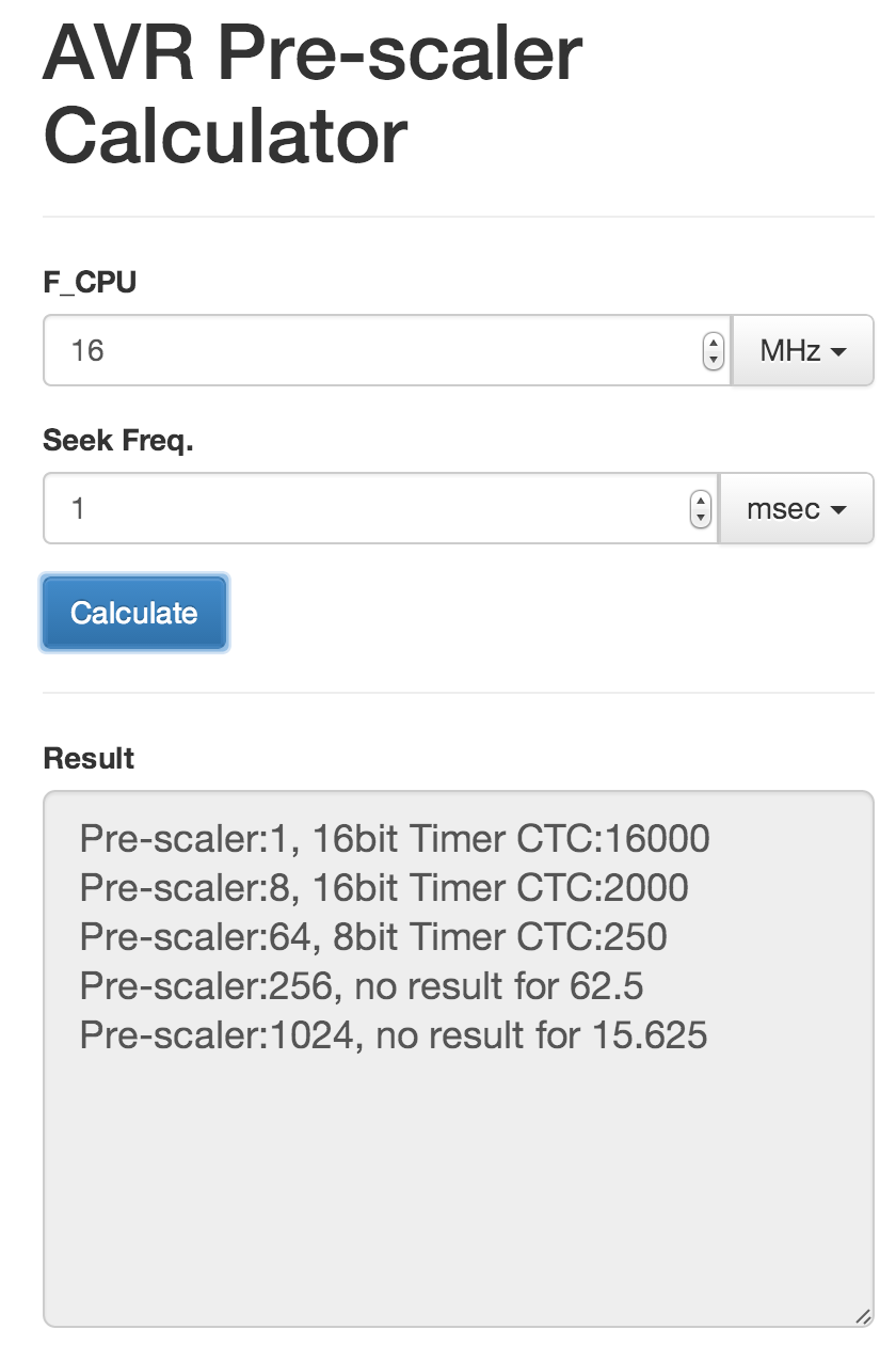
F_CPU は CPU クロック数、Seek Freq. のほうに欲しい周波数または時間間隔を入れて、Calculate を押すと、各分周比において CTC でいくつを設定すればいいか、あるいはオーバーフローでいけるかどうかとかを出す。
16MHz で 1msec を測りたい場合、
Pre-scaler:1, 16bit Timer CTC:16000
Pre-scaler:8, 16bit Timer CTC:2000
Pre-scaler:64, 8bit Timer CTC:250
Pre-scaler:256, no result for 62.5
Pre-scaler:1024, no result for 15.625