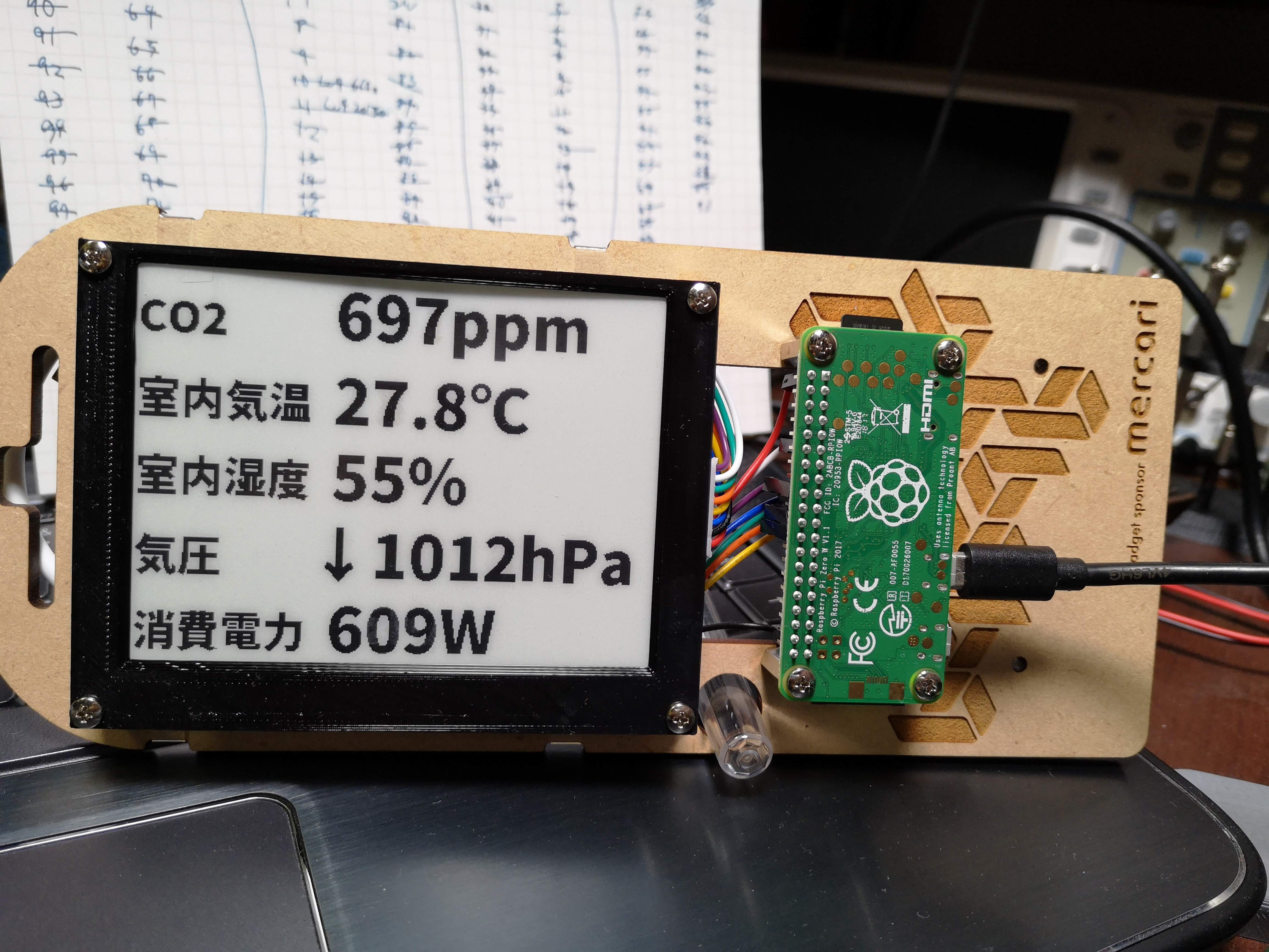
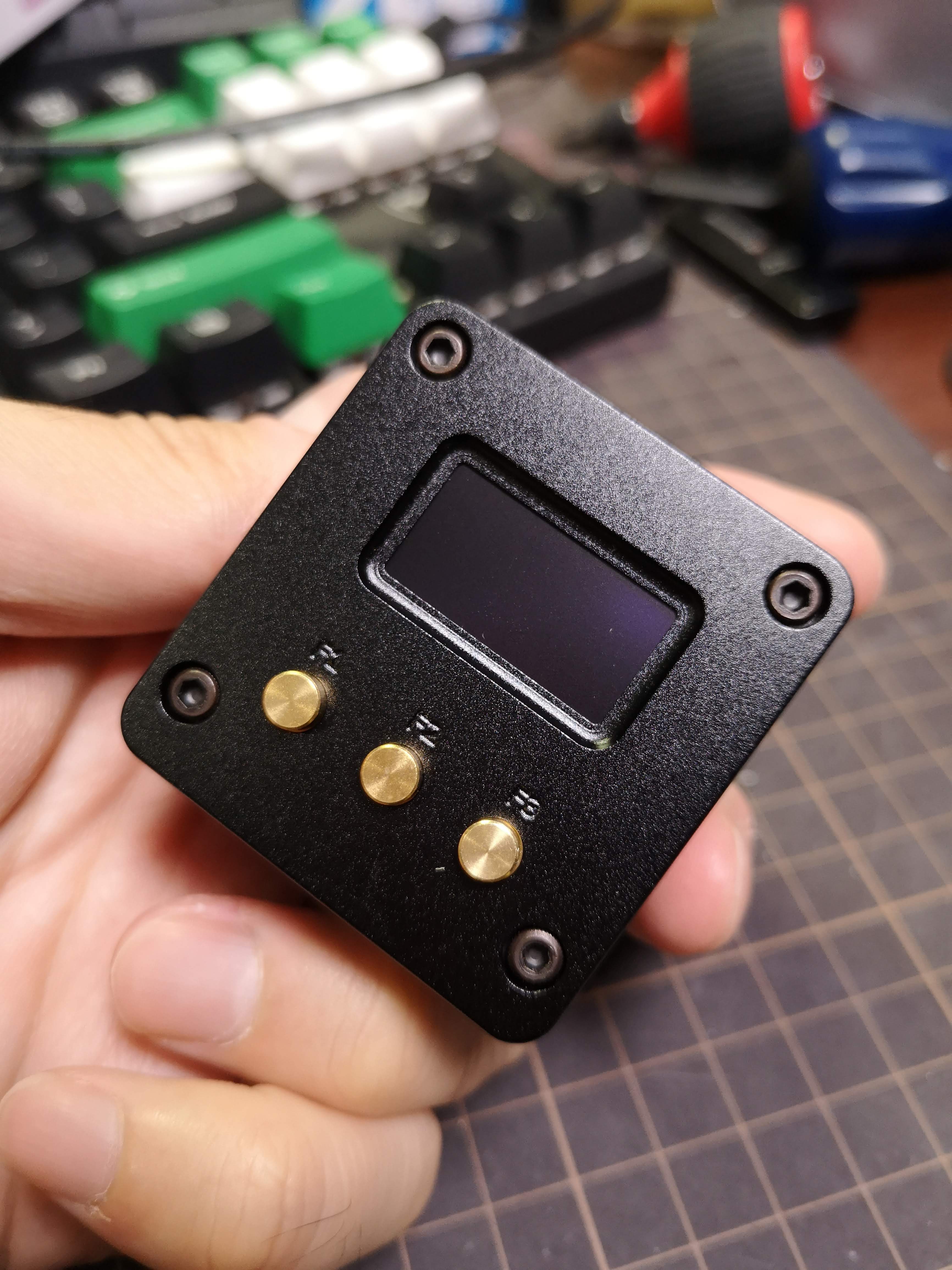
画面外になる部分が partial update でもチラチラ更新されてしまうので、これを隠すためにフレームをつくってつけた。
画面外になる部分が partial update でもチラチラ更新されてしまうので、これを隠すためにフレームをつくってつけた。
![]()
![]()
![]()
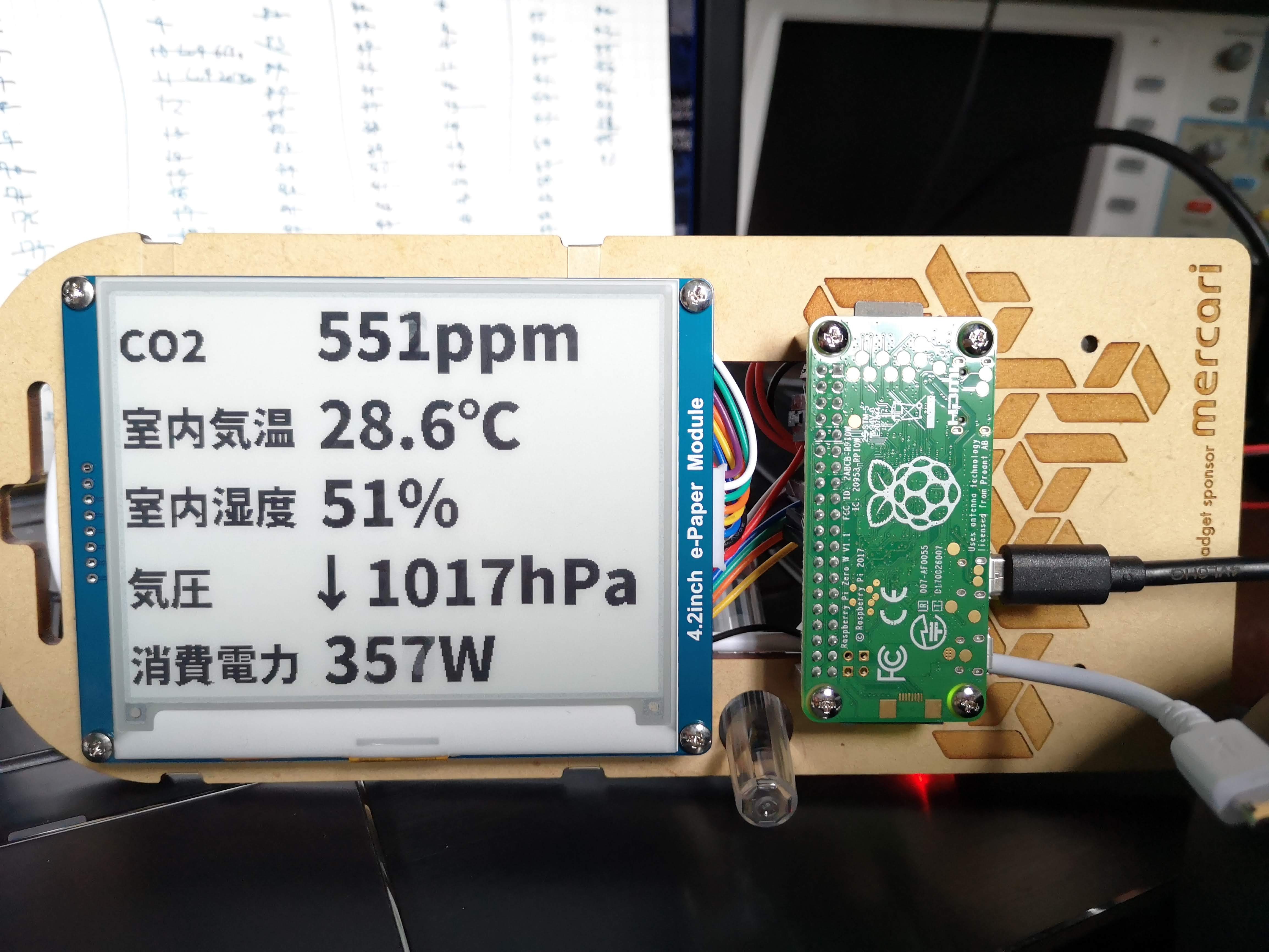
だけ。 表示部分はせっかく python の骨格があるので基本的にはそのまま python で書いてる。けど Pillow (python の画像処理ライブラリ) はそれほど高機能というわけではなくて、文字表示時に細かいオプションが一切指定できなかったりするので Ruby と Cairo とか慣れた他の方法でやったほうがよかったかも。
フォントは Noto Sans CJK の Black。Pillow が OTF をちゃんと読めてよかった。
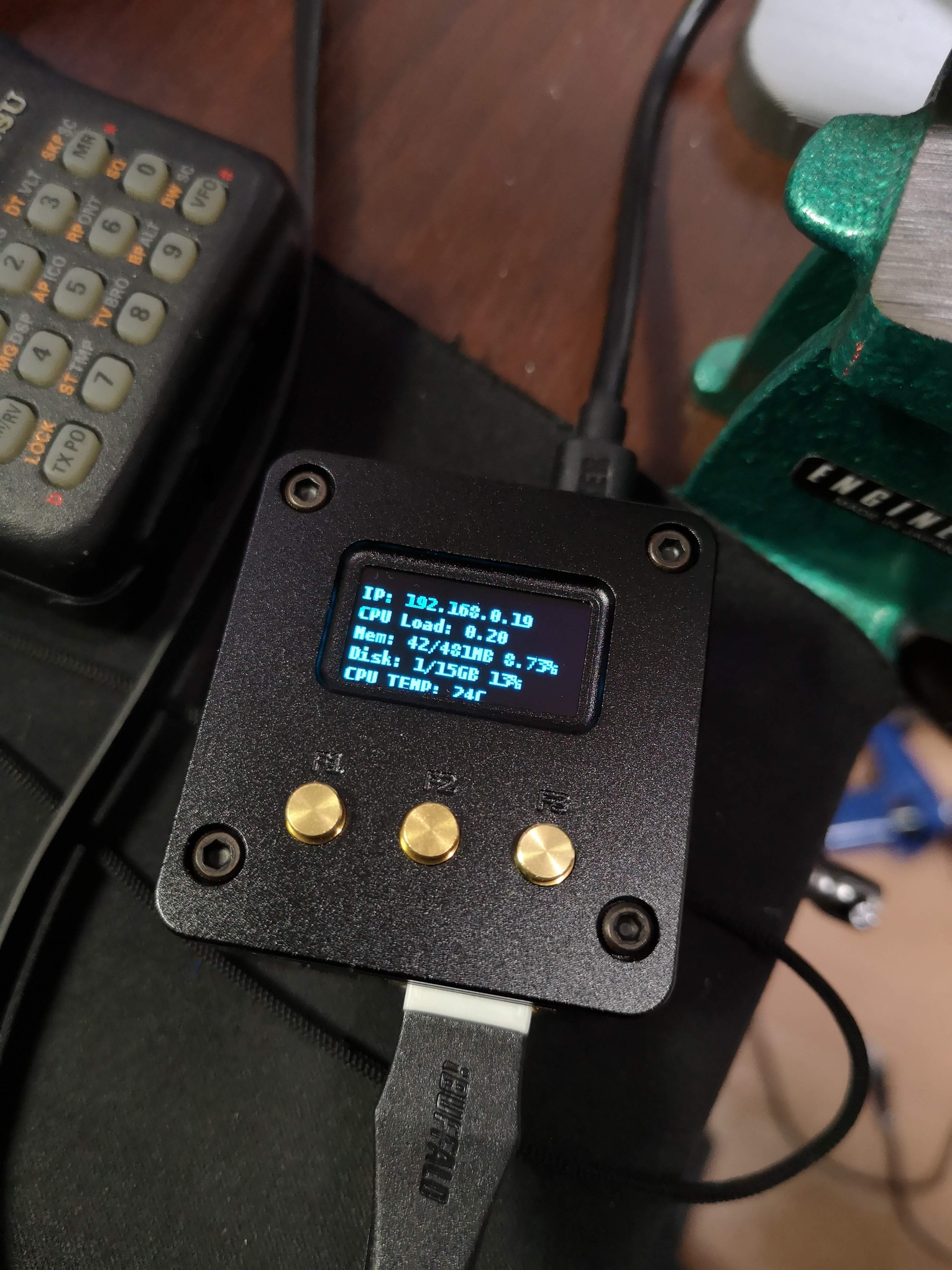
表示はフルリフレッシュを避けるように数値部分だけを部分書き換えしている。これにより表示更新が早くなるのと、フルリフレッシュ時みたいな全体が反転するチラツキがなくなるので常時していても邪魔くさく感じにくいはず。
↑ 試している様子 (値はランダム)。起動時はフルリフレッシュしてその後は常に部分書き換え
Ben Krasnow: Fast partial refresh on 4.2" E-paper display from Waveshare / Good Display の記事を参考に LUT をコピペしたらできたが LUT が何をしてるのかさっぱりわからない。
https://github.com/cho45/electronic_badge_2018/blob/partialupdate/sketch/sketch.py
lib/epd4in2.py とかにもかなり変更を入れてる。LUT まわりが↑のエントリの epd4in2.cpp からのコピペなのでライセンス的に微妙。
![]()
![]()
![]()
Waveshare 4.2 Black/White EPD
全体的な動作の説明がスペックに書いてないので正確にわかることがあんまりない。
Look-up Table。EPD 書き換えのときに、各フェーズでどのようにしてピクセルに電圧をかけるかを決めると思われる。
6バイトでワンセット、7回繰替えされる。42バイト(コマンドバイトを除く)。各状態遷移のときにパネルにどういう電圧のかけかたをするかを規定する。
以下のようなフルリフレッシュ用 LUT だと
    lut_wb = [
        0x80, 0x17, 0x00, 0x00, 0x00, 0x02,
        0x90, 0x17, 0x17, 0x00, 0x00, 0x02,
        0x80, 0x0A, 0x01, 0x00, 0x00, 0x01,
        0x50, 0x0E, 0x0E, 0x00, 0x00, 0x02,
        0x00, 0x00, 0x00, 0x00, 0x00, 0x00,
        0x00, 0x00, 0x00, 0x00, 0x00, 0x00,
        0x00, 0x00, 0x00, 0x00, 0x00, 0x00,
    ]
以下のような構造になる。
LUT_WB
lv: VDL GND GND GND
fr:  23   0   0   0 repeat: 2
lv: VDL VDH GND GND
fr:  23  23   0   0 repeat: 2
lv: VDL GND GND GND
fr:  10   1   0   0 repeat: 1
lv: VDH VDH GND GND
fr:  14  14   0   0 repeat: 2
lv: GND GND GND GND
fr:   0   0   0   0 repeat: 0
lv: GND GND GND GND
fr:   0   0   0   0 repeat: 0
lv: GND GND GND GND
fr:   0   0   0   0 repeat: 0
たぶん level select で指定した電圧を frame 数ぶんかける、そしてそれを repeat 数回行う、ということだと思う。違うかもしれない。VDH をかけると黒に、VDL にすると白になる。
VCOM とは? 名前からするに各ピクセルの共通側電圧の設定。他の LUT とあわせて共通側電圧をどうするかを設定すると思われる。基本的に他の LUT の frame、repeat 数とあわせて全状態で GND にしとけばいいっぽい。
6バイトでワンセット、7回繰替えされる。最後に2バイトつくので44バイト(コマンドバイトを除く)
VCOM
lv: GND GND GND GND
fr:  23   0   0   0 repeat: 2
lv: GND GND GND GND
fr:  23  23   0   0 repeat: 2
lv: GND GND GND GND
fr:  10   1   0   0 repeat: 1
lv: GND GND GND GND
fr:  14  14   0   0 repeat: 2
lv: GND GND GND GND
fr:   0   0   0   0 repeat: 0
lv: GND GND GND GND
fr:   0   0   0   0 repeat: 0
lv: GND GND GND GND
fr:   0   0   0   0 repeat: 0
B/W (白黒) モードの場合、DTM1 は "OLD" data を SRAM に転送する。DTM2 は "NEW" data を SRAM に転送する。
よくわからない。どっちも転送しておかないと、電圧かけたときに古いデータがでてきたりして謎。
仕様書のところどころで出てくる OTP って何?という話。
One Time Programming 1度だけ書きこみ可能なこと。E-paper の場合 LUT を OTP して固定することができる、ということらしい。とりあえず無視して良い。
![]()
![]()
![]()
mbed USBDevice ライブラリの中に USB CDC で動く USBSerial クラスが実装されている。これを Web USB から扱ってみる。これができるとブラウザ上から直接デバイスの設定などを行えるので便利になる。
LPC11U35 でも動かすことができる。
以下のような interface になっている。
CDC class (interface count = 2)
interface 0  (endpoint count = 1)
  CDC Header Functional Descriptor
  Call Management Functional Descriptor
  Abstract Control Management Functional Descriptor
  Union Functional Descriptor
  Endpoint Descriptor
    INTERRUPT IN (interval = 16)
interface 1 (endpoint count = 2)
  Endpoint Descriptor
    BULK IN (endpoint num = 2)
  Endpoint Descriptor
BULK OUT (endpoint num = 2) シリアル通信まわりだけだと以下のようになる
#include "mbed.h"
#include "CircBuffer.h"
#include "stdint.h"
#include "USBCDC.h"

class MyUSBSerial: public USBCDC {
	private:
		Callback<void()> rx;
		CircBuffer<uint8_t,128> buf;

	public:
		MyUSBSerial(uint16_t vendor_id = 0x1f00, uint16_t product_id = 0x2012, uint16_t product_release = 0x0001, bool connect_blocking = true):
			USBCDC(vendor_id, product_id, product_release, connect_blocking){
			};

		bool writeBlock(void* b, uint16_t size) {
			uint8_t* buf = reinterpret_cast<uint8_t*>(b);
			if (!send(buf, size)) {
				return false;
			}
			return true;
		}

		uint8_t available() {
			return buf.available();
		}

		void read(uint16_t len, uint8_t out[]) {
			while (available() < len);
			for (uint16_t i = 0; i < len; i++) {
				buf.dequeue(&out[i]);
			}
		}

		uint8_t read() {
			uint8_t c = 0;
			while (available() < 1);
			buf.dequeue(&c);
			return c;
		}

		bool connected() const {
			return terminal_connected;
		}


	protected:
		virtual bool EPBULK_OUT_callback() {
			uint8_t c[MAX_PACKET_SIZE_EPBULK+1];
			uint32_t size = 0;

			//we read the packet received and put it on the circular buffer
			readEP(c, &size);
			for (uint32_t i = 0; i < size; i++) {
				buf.queue(c[i]);
			}

			//call a potential handlenr
			if (rx)
				rx.call();

			return true;
		}

		virtual void lineCodingChanged(int baud, int bits, int parity, int stop){
			// nothing to do
		}
};

MyUSBSerial usbserial(0xf055, 0xf001);

int main(void) {
    while (1) ;
} こちらもシリアル通信にあたる部分だけ。
を指定して transferIn/transferOut をすれば良い。DTR などを設定するために controlTransferOut も使うが、ただデバイスとやりとりするだけなら特に必要はない。
以下のような感じ。
const CDC_SET_LINE_CODING        = 0x20;
const CDC_GET_LINE_CODING        = 0x21;
const CDC_SET_CONTROL_LINE_STATE = 0x22;
const CLS_DTR  = (1 << 0);
const CLS_RTS  = (1 << 1);
const INTERFACE_INDEX = 1;
const ENDPOINT_INDEX = 2;

class USBCDC {
	constructor() {
		this.onread = () => {};
	}

	async connect(filters) {
		this.device = await navigator.usb.requestDevice({
			filters: filters || [
				{ 'vendorId': 0xf055, 'productId': 0xf001 }
			]
		});
		console.log(this.device);

		const read = async () => {
			const result = await this.device.transferIn(ENDPOINT_INDEX, 64);
			this.onread(result.data.buffer, result);

			if (result.status === 'stall') {
				console.warn('Endpoint stalled. Clearing.');
				await this.device.clearHalt(1);
			}
			read();
		};

		const configuration = await this.device.open();
		if (this.device.configuration === null) {
			await this.device.selectConfiguration(1);
		}

		await this.device.claimInterface(INTERFACE_INDEX);
		await this.device.controlTransferOut({
			'requestType': 'class',
			'recipient': 'interface',
			'request': CDC_SET_CONTROL_LINE_STATE,
			'value': CLS_DTR,
			'index': INTERFACE_INDEX
		});
		read();
	}

	async write(data) {
		if (typeof data === "string") {
			// string to utf-8 arraybuffer
			const arraybuffer = await new Promise( (resolve, reject) => {
				const reader = new FileReader();
				reader.onloadend = function () {
					resolve(reader.result);
				};
				reader.readAsArrayBuffer(new Blob([data]));
			});
			console.log('write ab', arraybuffer);
			await this.device.transferOut(ENDPOINT_INDEX, arraybuffer);
		} else {
			console.log('write rr', data);
			await this.device.transferOut(ENDPOINT_INDEX, data);
		}
	}

	async close() {
		await this.device.controlTransferOut({
			'requestType': 'class',
			'recipient': 'interface',
			'request': CDC_SET_CONTROL_LINE_STATE,
			'value': 0x00, // reset DTR
			'index': INTERFACE_INDEX
		});
		await this.device.close();
	}
}

const usbcdc = new USBCDC();
btnConnect.onclick = async () => {
	usbcdc.onread = (buffer, result) => {
		console.log(result);
		console.log(String.fromCharCode.apply("", new Uint8Array(buffer)));
	};
	usbcdc.connect();
};
![]()
![]()
![]()
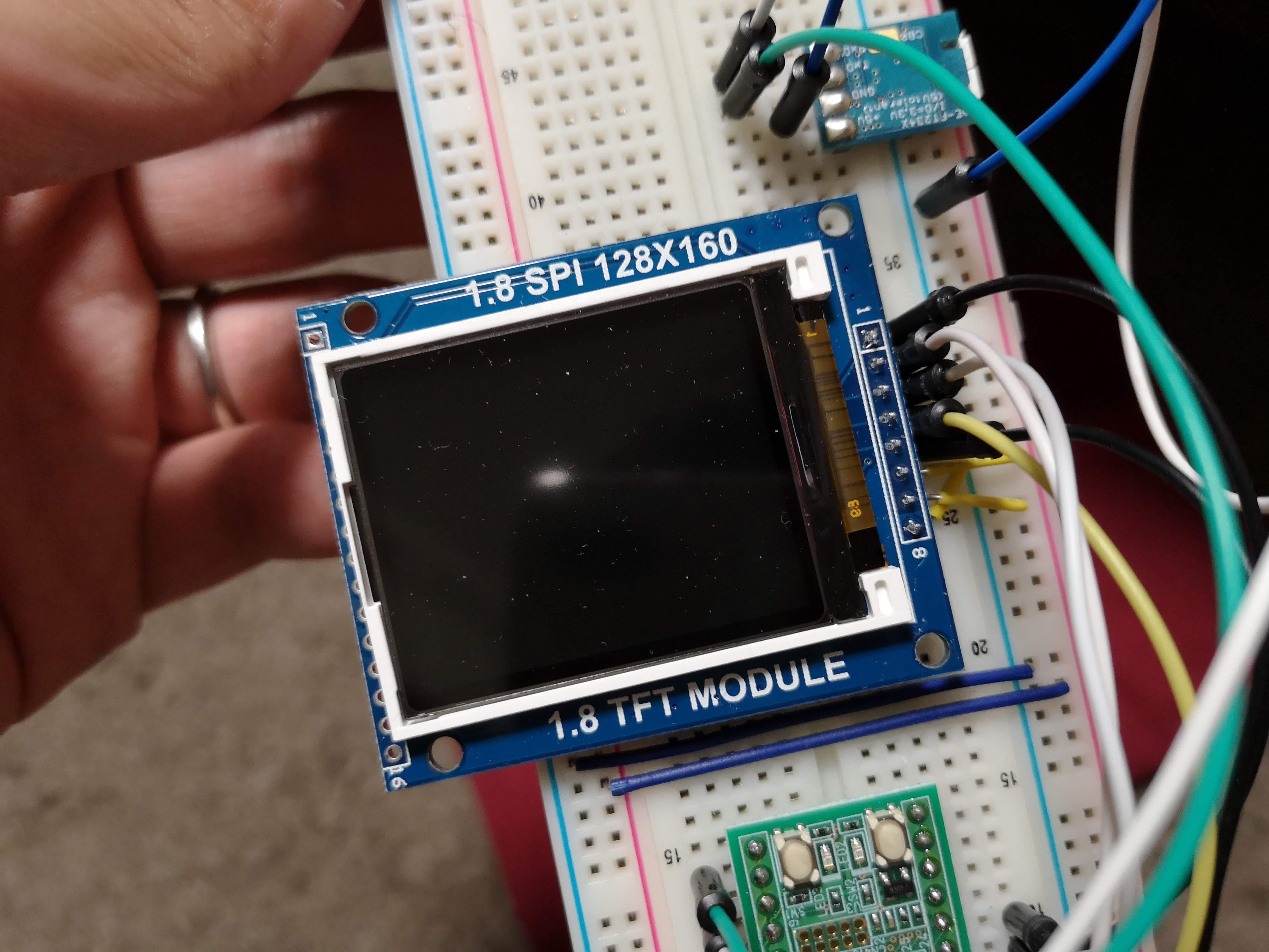
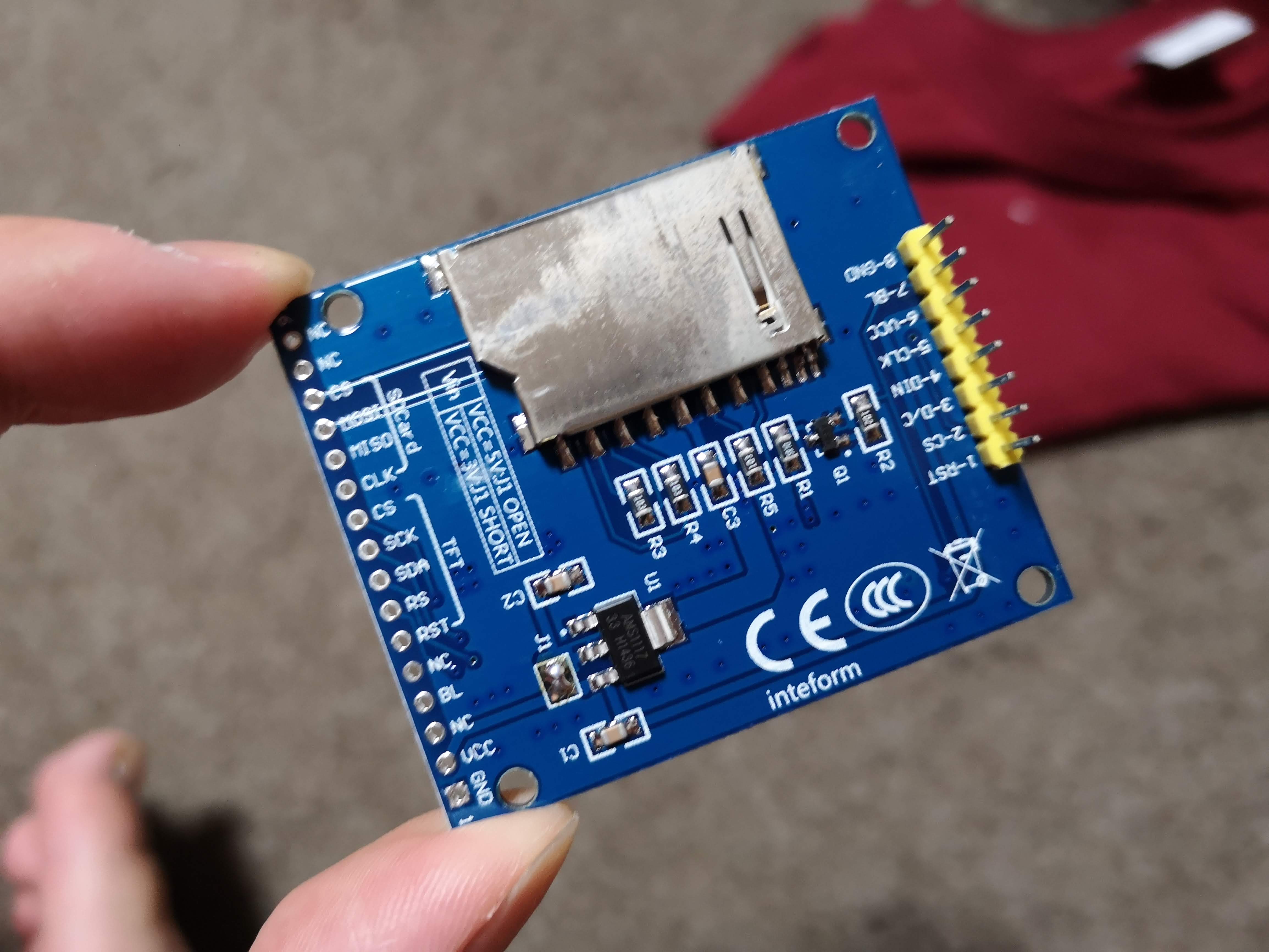
だいぶ前に買ったのを放置してたので動かした。なぜかSDカードコネクタとかついてる。最初は 5V インターフェイスでレギュレータを使うようになっているが、ジャンパで 3.3V にすることができる。
「Adafruit_ST7735」という名前のライブラリがいくらか公開されているので、それを参考にちょっと書きかえた。ST7735 シリーズは細かい違いがたくさんあるようでなかなか難しい。
このライブラリは setRotation するときに MADCTL を発行するが、RGB と BGR の選択もコマンドで設定を行うため、setRotation をすると色が反転するみたいなことが起きて困った。
基本的には setAddrWindow して更新範囲を指定して pushColor して更新する。
	tft.setAddrWindow(offsetx, offsety, offsetx + width - 1, offsety + height - 1);
	for (int y = 0; y < height; y++) {
		for (int x = 0; x < width; x++) {
			usbserial.read(2, buf);
			uint16_t c = (buf[0] << 8) | buf[1];
			tft.pushColor(c);
		}
	}
![]()
![]()
![]()
Rock64 http://akizukidenshi.com/catalog/g/gM-12382/ というのを買ってみた。
とりあえず minimal Ubuntu をいれた。
ssh は最初から有効。rock64:rock64 で入れる。
sudo /usr/local/sbin/rock64_diagnostics.sh -m
便利ツールが最初からある。
そこそこ大きめのヒートシンクをつけてもCPUにフルロードかけると78℃近くまでいく。たぶんヒートシンク必須。だけどCPUクロックに制限かかるまではいかない。というかクロック制限はあるのだろうか?
ちなみにアイドル時にはクロックダウンする。
GPIO2_A2/IR_RX/POWERSTATE2_u M21 に IR Receiver が繋っているが使いかたがよくわからない。RK3328 自体で NEC フォーマットの IR コマンドをサポートしているみたいだが Linux から利用するドライバがよくわからない。
まぁ GPIO 機能もあるので、こっちで読み出しをしてみることにしてみた。
GPIO2_A2 (2_A2 の部分を変換して pin 番号を求める) は 2 * 32 + ("A".charCodeAt(0)-65) * 8 + 2 = 66
root@rock64:/home/rock64# echo 66 > /sys/class/gpio/export
試しに IRKit に使えるフォーマットで受信データを表示するようにしてみた。IRKit は 2MHz sample のカウント数で表示されるので変換している。
//#!/usr/bin/env go run
package main

import (
	"fmt"
	"time"

	"github.com/brian-armstrong/gpio"
)

type Event struct {
	th int64
	tl int64
}

func main() {
	watcher := gpio.NewWatcher()
	watcher.AddPin(66)
	defer watcher.Close()

	events := make(chan *Event)

	go func() {
		prev := time.Now()
		var th int64 = 0
		var tl int64 = 0
		for {
			now := time.Now()
			delta := now.Sub(prev).Nanoseconds()
			prev = now
			_, value := watcher.Watch()
			switch value {
			case 1:
				tl = delta
				events <- &Event{th, tl}
			case 0:
				th = delta
			default:
			}
		}
	}()

	for {
		e := <-events
		fmt.Printf("%d %d\n", e.th/5.0e2, e.tl/5.0e2)
	}
}
IR 受信にはsys/gpio だと速度がちょっと足りないですね。
![]()
![]()
![]()
さくらのVPSはIPv4/IPv6デュアルスタックで、双方ともにグローバルアドレスがついているため、IPv4 しかない環境から IPv6 アドレスがついたホストへ SSH する際の踏み台に使うことができる。
Host raspberrypi
User pi
Hostname 2001:db8::40c0
ProxyCommand ssh user@vpshost -W '[%h]:%p'
自宅のIPv6環境でアクセスする場合は、ルーターなどのファイアーウォールの設定が必要。家庭用ルーターはIPv6でも無防備にならないように、デフォルトでほとんどのインカミングパケットを破棄するので、特定ホスト・ポートへのアクセスを許可する設定が別途必要となる。
![]()
![]()
![]()
まず BME280 と BMP280 というよく似たやつがあるので注意…。 BMP は気圧と気温しか測れない。
リセット直後の BME280 は圧力・温度・湿度すべての測定がスキップかつスリープモードになっているので、まず測定開始するように設定する必要がある。いくつかモードがあるが、とりあえず NORMAL モードにして定期的に値を更新するようにしとけば良い。
なお用途に応じて最適と思われる設定がデータシートで示されているので、それに従えば良い。
FORCED モード (ワンショットモード) で測定する場合、9. Appendix B: Measurement time and current calculation を参照して tmeasure を求める必要がある。FORCED モードは MODE に書きこむと測定が始まり、終わると SLEEP モードになるという挙動をする。
ググるとほかにも実装が出てくるが、まずはリファレンス実装で試すのが筋。
https://github.com/BoschSensortec/BME280_driver
メーカーがリファレンス実装をつくってる。
$ git clone git@github.com:BoschSensortec/BME280_driver.git
$ cd BME280_driver
$ gcc -DBME280_FLOAT_ENABLE -I. -o foo examples/linux_userspace.c bme280.c
$ ./foo /dev/i2c-1
Temperature, Pressure, Humidity
temp 31.10, p 100605.10, hum 48.97
temp 31.10, p 100605.08, hum 49.01
temp 31.11, p 100605.11, hum 48.97
temp 31.12, p 100605.34, hum 48.98
temp 31.13, p 100605.46, hum 49.02
https://github.com/cho45/ruby-i2c-devices/blob/master/lib/i2c/device/bme280.rb
に書いた。calibration データの扱いに地味にハマってなかなかうまくいかなかった。
![]()
![]()
![]()
↑ に一応資料をあげときます。めっちゃ酔っぱらってこのエントリを書いております。
mbed 環境は Arduino の次あるいはプログラマなら最初の一歩として本当にお勧めです。若干価格が高いのが玉に傷ではありますが、LPC11U35 Quickstart Board は比較的導入しやすく、mbed 入門・USB デバイス入門に最高だと思っています。ぜひ mbed 環境を試してみてほしいと思います。
もともとキーボードに使っていた BLE Nano も mbed です。これも BLE デバイスとしては非常に安価な部類だと思います。僕は今のところ挫折していますが、ぜひ安定したBLEデバイスを作ってノウハウを教えてください……
builderscon は本当に良くて、今回はスピーカーディナー(スピーカーといろんな人同士の交流)という新しい試みも大変楽しかったです。前夜祭はやっぱりオフレコの闇の話が最高に楽しいですね。
builderscon はリアルイベントなのにインターネットの夜明けのような希望があります。こういうイベントは本当に貴重で、運営のかたには頭が上がりません。まだ builderscon はこれからですが楽しみたい!!
![]()
![]()
![]()
5年ごとの更新日がきたので旧免許状を返納した。新免許状は4月ぐらいに届いてたのでやることは返納のみ。しかし返納先がいつもいつも謎。
新免許に返納先の案内を入れてくれればいいのに。
もしかして返納しなくてもいいんだっけ??ってぐらいの雑さだけど、30日以内に返納しないと30万円以下の過料が課される。なんやねん……
![]()
![]()
![]()
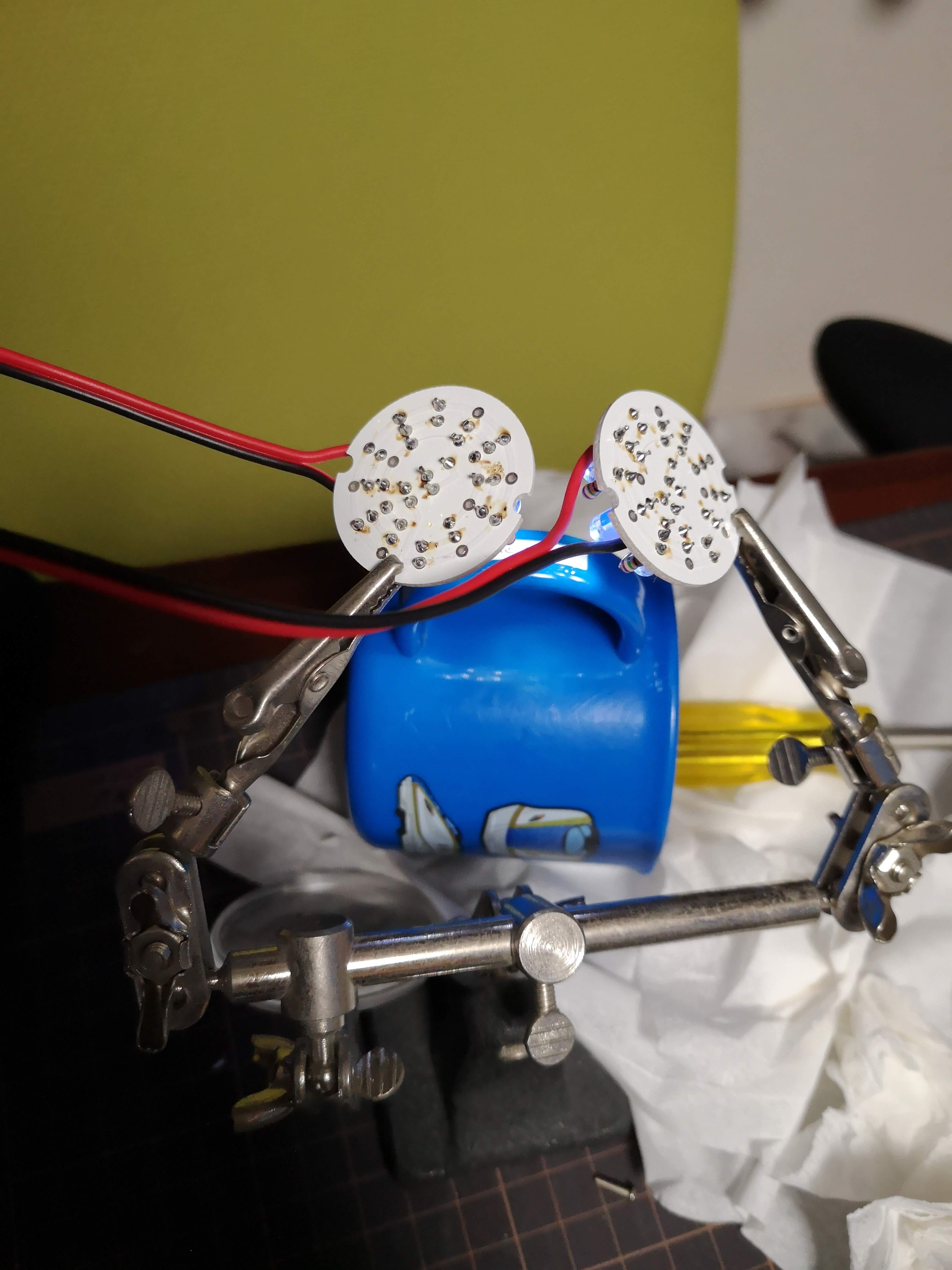
子どもの持ち物には記名する必要があるが、たびたび洗う必要のあるものはどうしても記名自体が長持ちしない。
何とかならないか考えた結果UVレジンで表面をコーティングしてみることにした。透明度が高くコーティングしても目立たないこと、硬化してしまえば安定してること、紫外線で硬化のため扱いやすく 硬化時間が短いこと、あたりが魅力的。
UVレジンは耐熱性が低い(70℃程度)ようなので食洗機で不安。一回洗ったぐらいではなんともなさそうだが、繰り返し熱を加えられたときどうなるか微妙かもしれない。
使ったレジンはキヨハラというメーカーのこれ。さらさらではなく適度に粘性があり、囲いなどが無くても勝手に流れていくようなことはなかった。

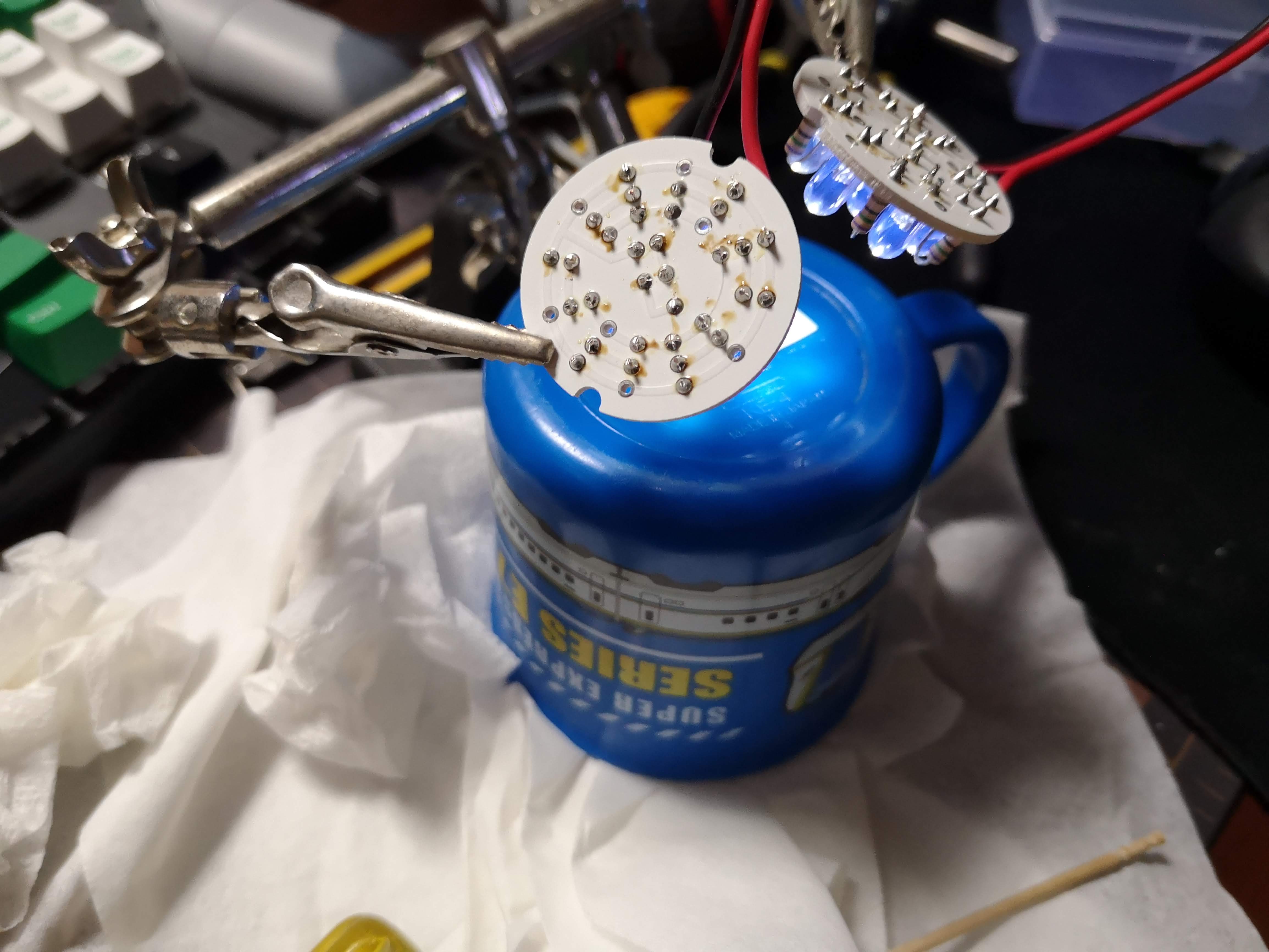
硬化はUV LED 14個 OptSupply OSV1YL5111A (30円)。1本あたりの放射束が2〜4mW(@20mA)とかなり効率が悪い。日亜化学工業の 375nm NSPU510CS (500円) は 15.1mW (@15mA) なので効率は6分の1以下。ただし価格は圧倒的に OSV1YL5111A が安いので同じ放射束を得るには4分の1程度のコストで良い (ただし消費電力とトレードオフ)。
30分ぐらいで完全硬化した。375nm 365nm を混ぜたが365nmだけで良かったかも。時間かかるので、このLEDを使うならもうちょい数が多いほうが良さそう。
![]()
![]()
![]()
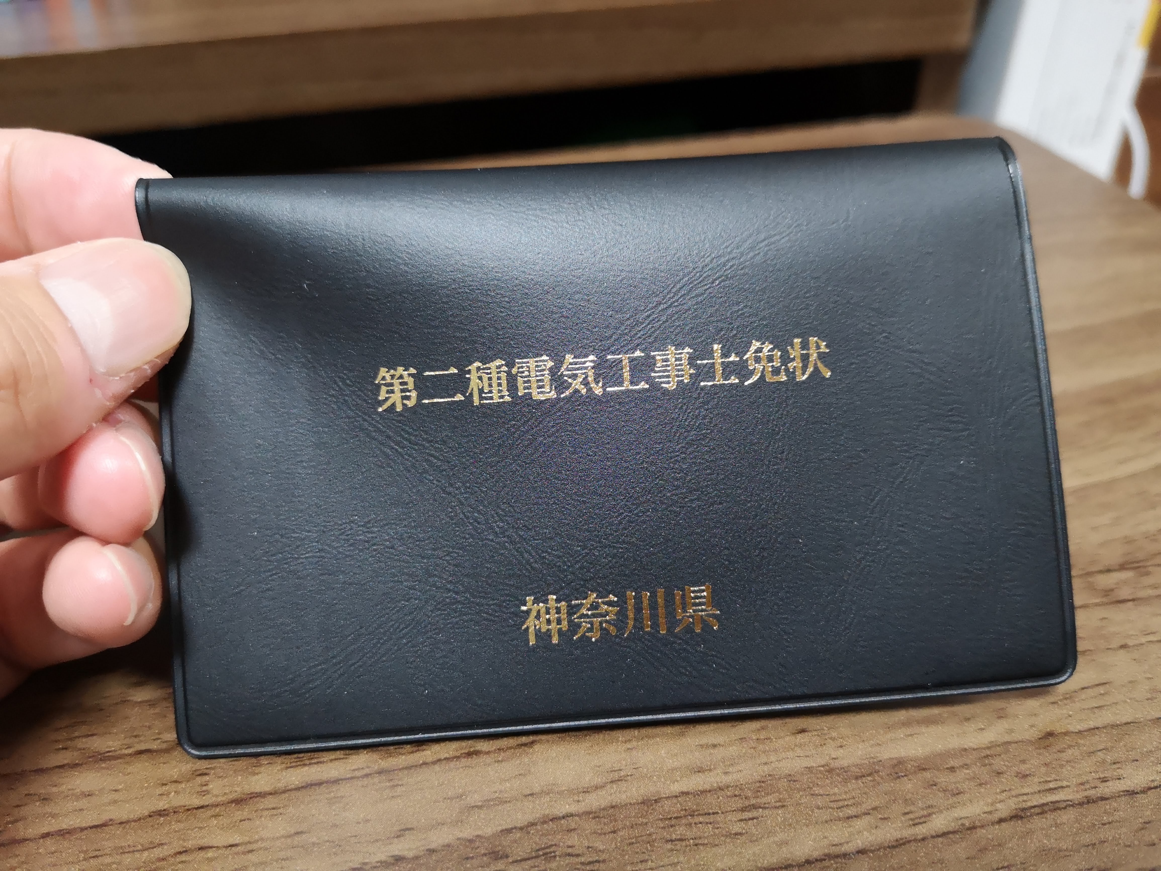
第二種電気工事士 試験終わり | tech - 氾濫原 昨日に不在票が入っていたので、申請から到着まで5日だった。2週間ぐらいと言われてたが早かった。免許日は27日。
![]()
![]()
![]()
公式の Wiki を見るとわかるのだが、Nano Pi NEO 2 には V1.0 と V1.1 (LTS) の2つのバージョンがある。スペック的には一緒なのだけど、コネクタ位置が微妙に異るため、それぞれ専用に設計されたケースに互換性がない。
例えば V1.0 には 3D プリント用のモデルがある NanoPi NEO2's 3D printed housing
が、V1.1 にはない。
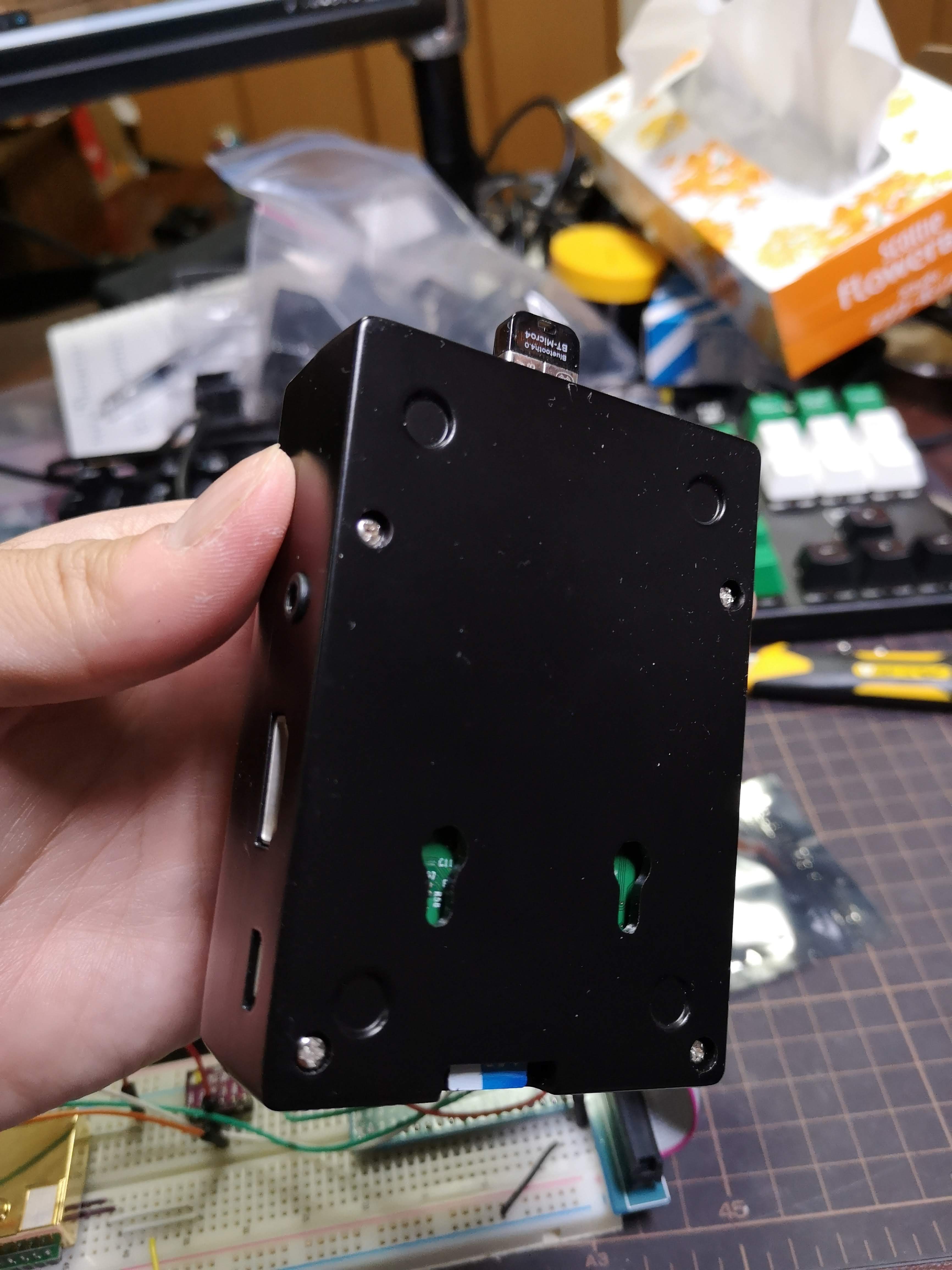
一方で V1.1 用にはシャレたアルミケースとOLEDのキットがある。写真はこれを使った V1.1 版のもの。
タイトルの通りだけど秋月電子通商で買えるのは前者のバージョンになる。
アルミケース+OLEDを買ったあとに秋月で本体を購入したところ初めてあわないことに気付いた。罠すぎる。結局 V1.1 も Friendly Elec の公式通販から買ってしまった (ちなみに公式の通販ではヒートシンクが付属しているので、余計に買わないように…… ヒートシンクも余計に買ってしまって二重に失敗してる)
間違えて買った V1.0 は 3D プリンタでケースを用意して普通に使っている。
V1.1 のアルミケースはかなり可愛いのでなにかに使いたいが特に用途は決まってない。
![]()
![]()
![]()
ebay で売っていたものを買ってみた。810円ぐらい。ABSのケースが1000円で売ってたりするので、かなりお得なのではないか? 放熱用にカバー側に突起がついてておもしろいが、うまく接触するのかよくわからない。
![]()
![]()
![]()